
1.2G 0.1mW/25mW/200mW/800mW VTX & VRX - 9CH Transmitter Receiver FPV Video System Combo for RC Models Drone Quad Enhancement Booster
-
Detail
1.2G 0.1mW/25mW/200mW/800mW & SPECIFICATIONS
Brand Name: Readytosky
Is Electric: No battery
Origin: Mainland China
Material: Composite Material
Recommend Age: 14+y
RC Parts & Accs: Radio Systems
For Vehicle Type: Airplanes
Use: Vehicles & Remote Control Toys
Remote Control Peripherals/Devices: RECEIVERS
Tool Supplies: Cutting
Technical parameters: Value 6
Model Number: 1.2Ghz 1.2G
Four-wheel Drive Attributes: Assemblage
Wheelbase: Screws
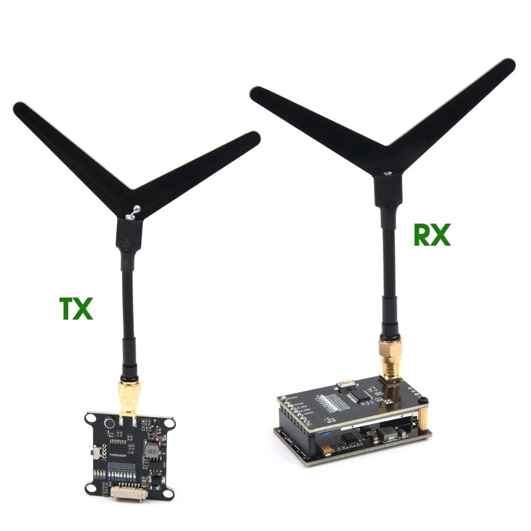
Transmitter:I. Button control and LED indicators
1. Green indicator 4pcs are power indicators, they are: 0.1mW(0)/25mW(D)/200mW(C)/800mW(H).
(D)/200mW(C)/800mW(H), the default is 0.1mW when the power is on.
to the next power level. This operation can be cycled and the corresponding power indicator will light up every time you press and hold the button.
The corresponding power indicator will light up each time you press and hold the button. Note: The transmitting power must be readjusted after each power failure.
II. The 9 red LEDs are frequency indicators.
This operation can be cycled, each short press on the corresponding frequency point indicator will light up.
Note: The operating system has a memory function, the system will save the current frequency point after power failure. II. Interface definition:
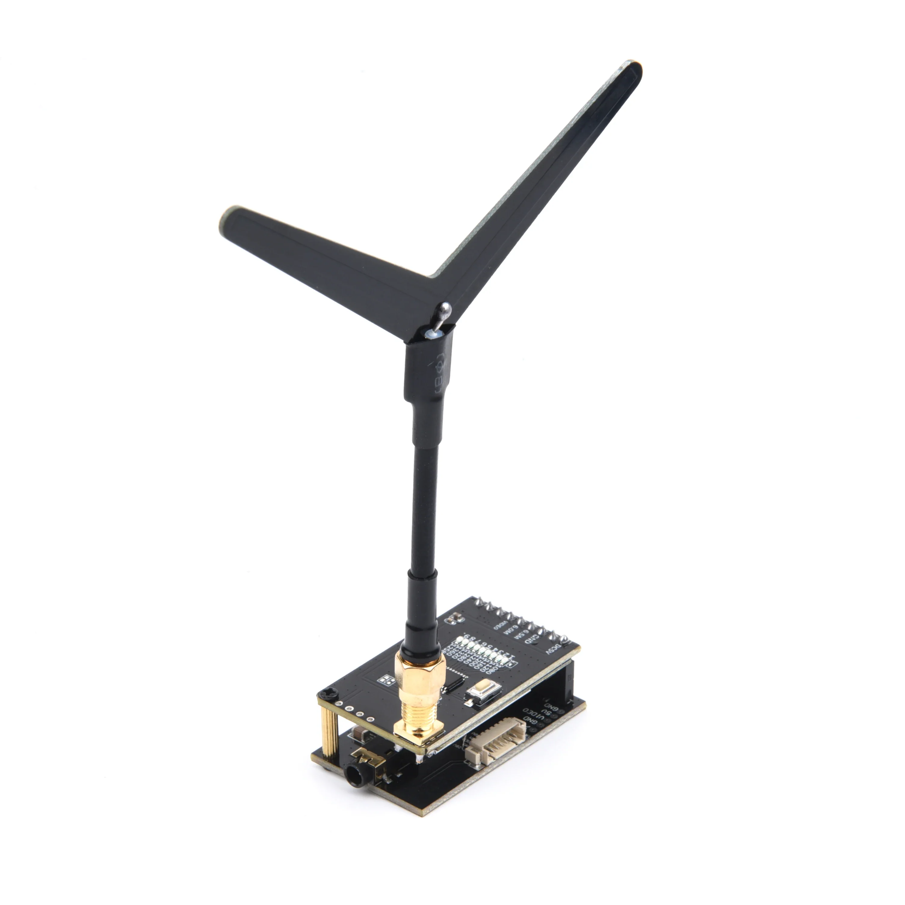
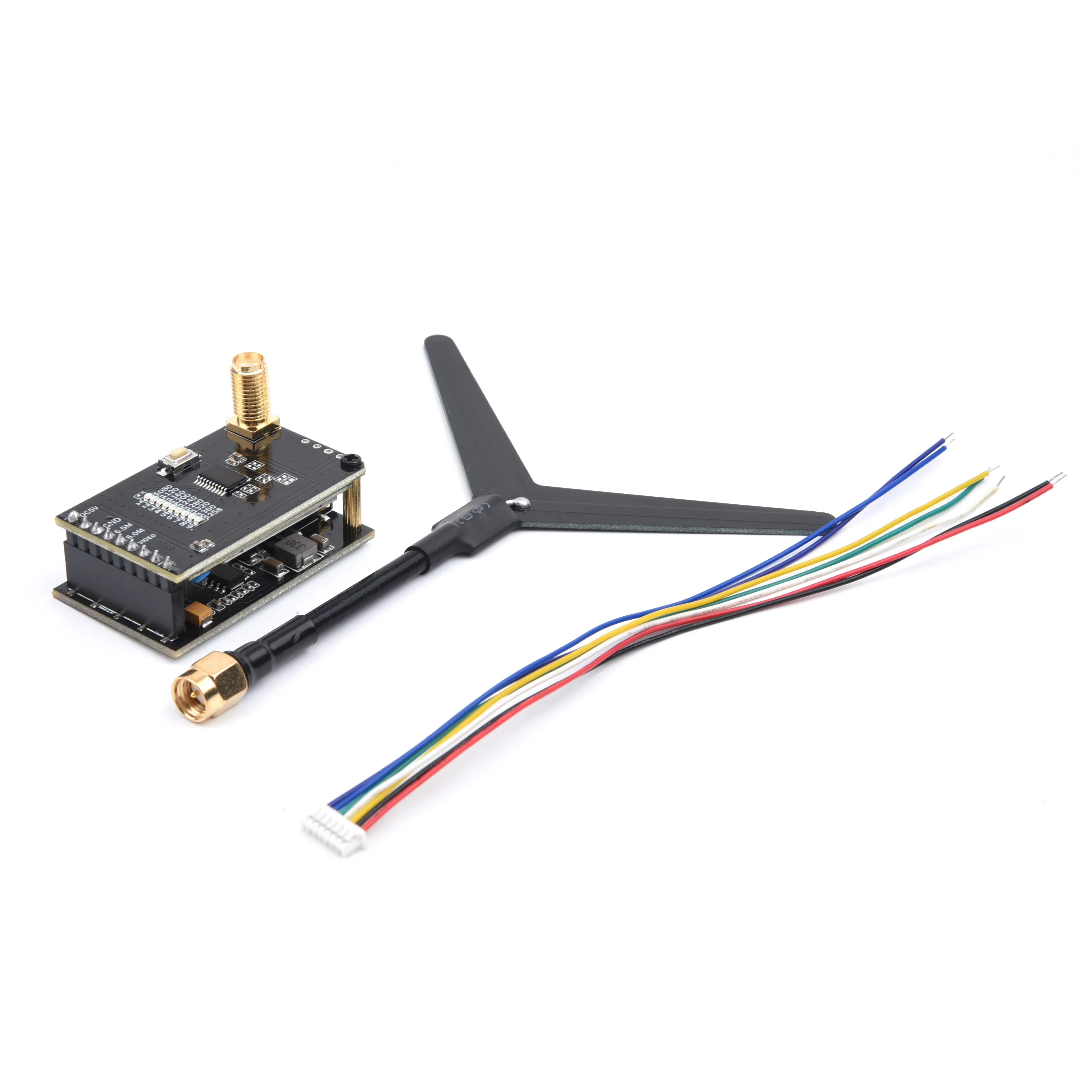
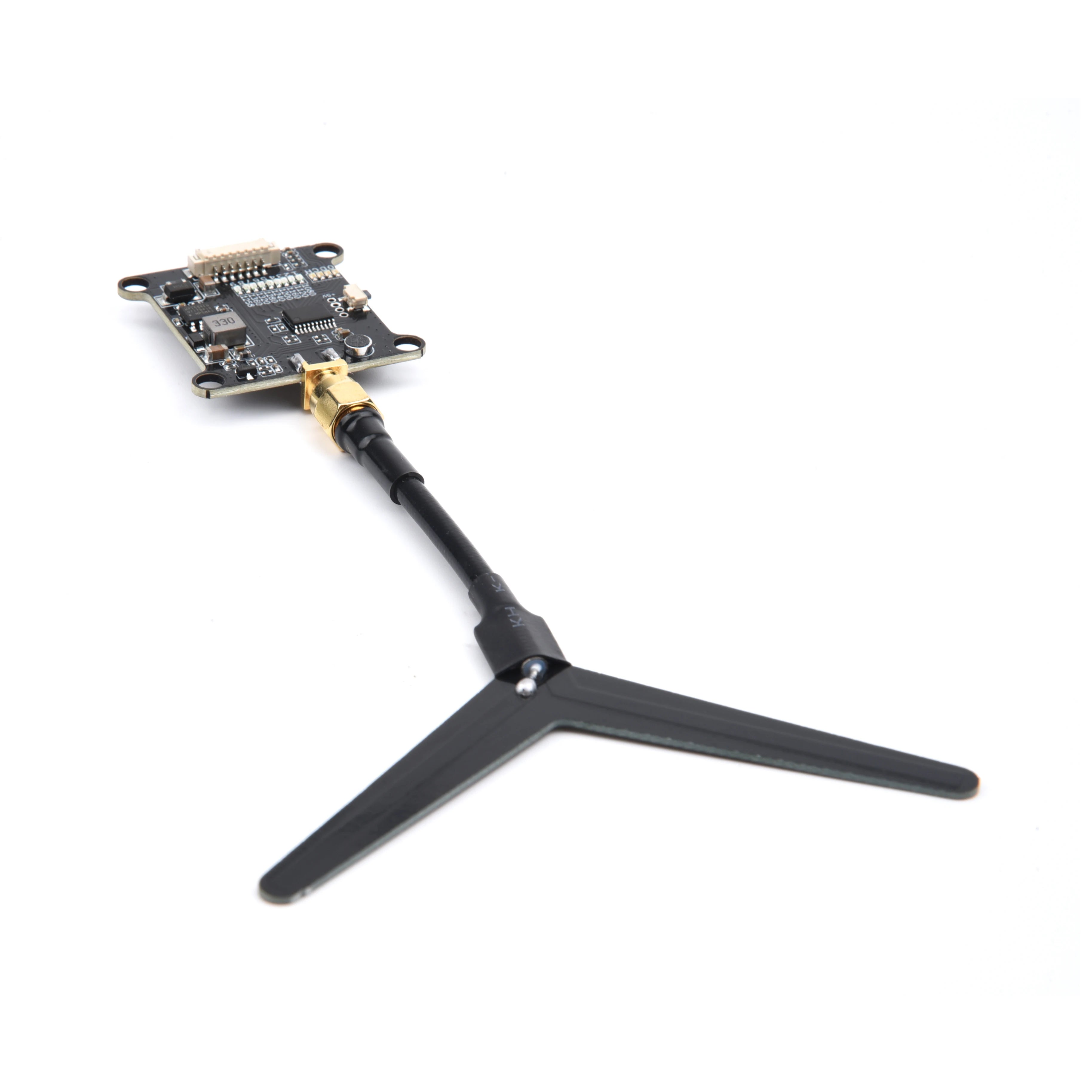
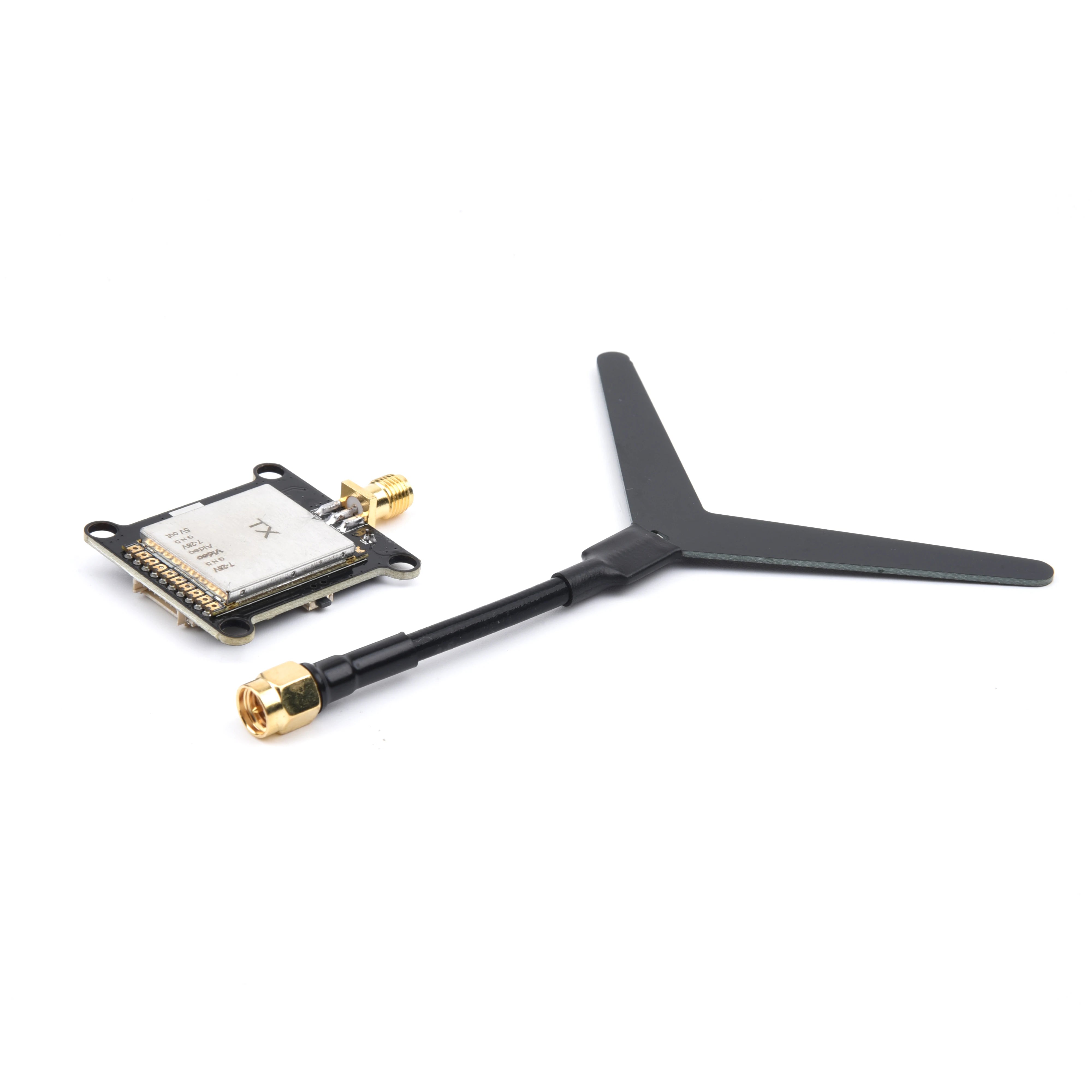
The antenna is SMA interface; the antenna head is "male thread + hole" and the antenna pole is "female thread + pin".
Pin" configuration 1.2G special customized "Y" type antenna.
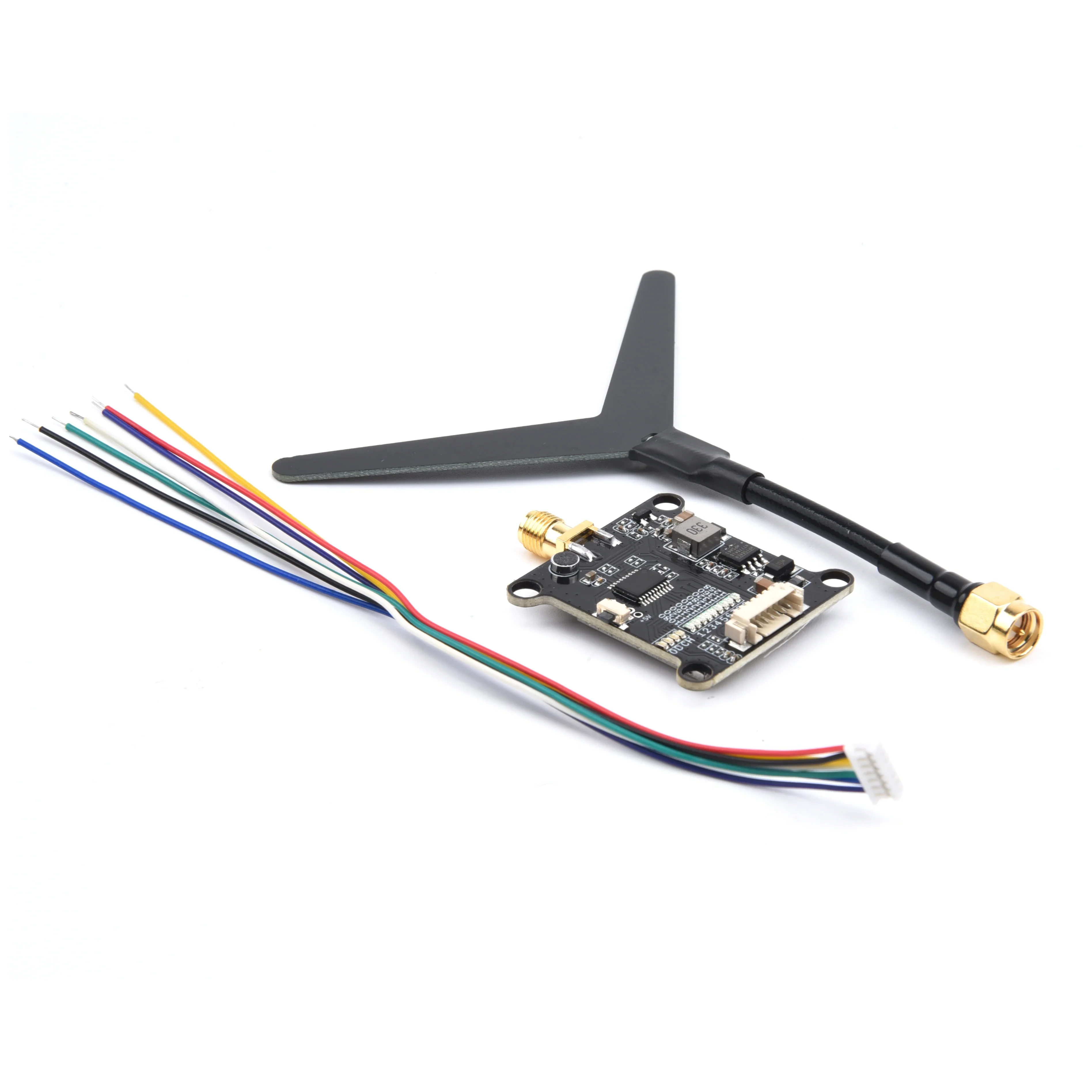
2.7P1.25
The sequence of the socket connection is:
1. power input DC 7-28V;
2. input ground;
3. video input;
4. 6.5M audio input;
5. DC output 7-28V;
6. DC output ground;
7. DC output 5V.
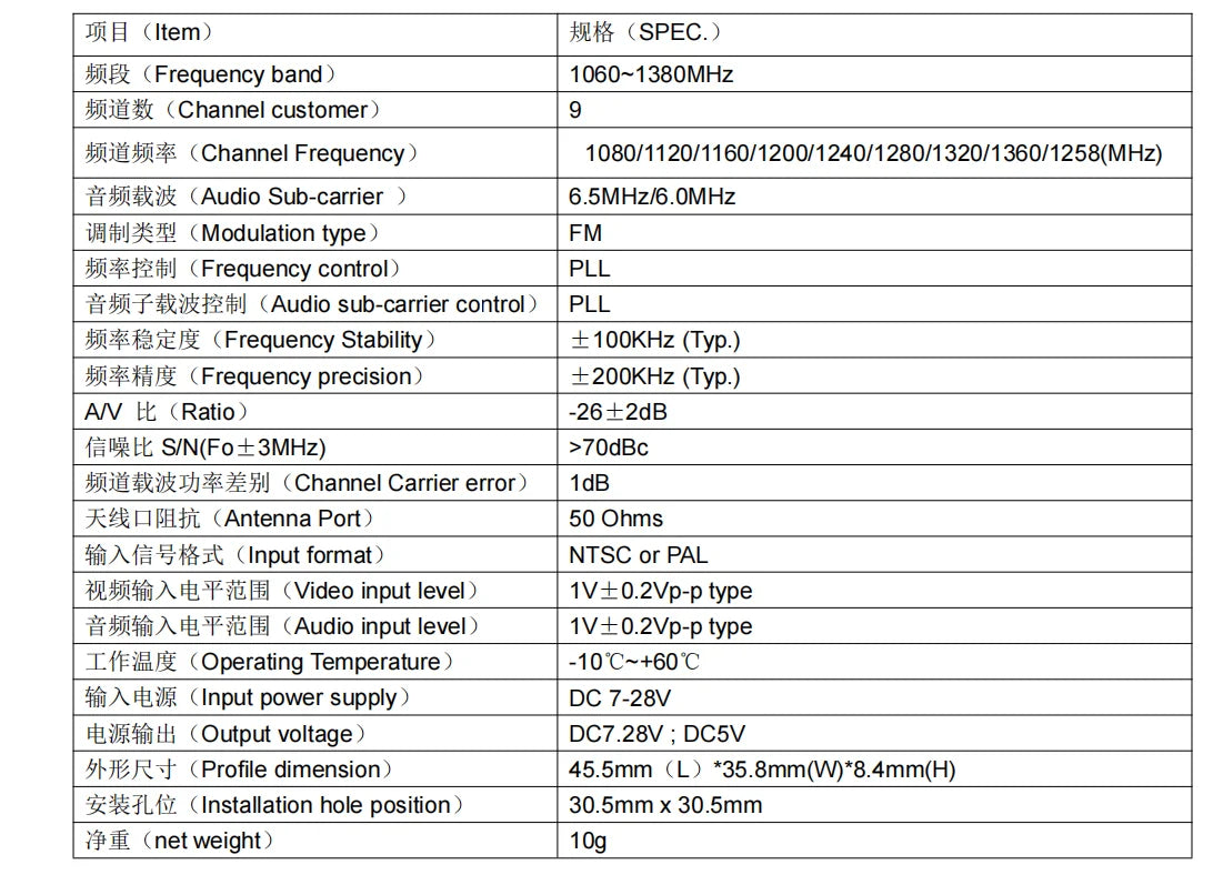
This system has an absolute frequency ratio of -26 dB to +2 dB, with all signal frequencies above 3 MHz having greater than 70 dBc carrier error. It operates on a 50-ohm impedance and supports input formats NTSC or PAL. The video input level is 1V (peak-to-peak) with a type 4:4:4 color format and +/- 4A frequency response. The audio input level is also 1V, with a peak-to-peak amplitude of +/- 0.5V.
Receiver:I: Button control and LED indicatorsThe 9 red indicators are the frequency point indicators and are switched to the next frequency point by pressing the button once.This operation can be cycled, each short press of the corresponding frequency point indicator will light up.Note: This operating system has a memory function, the system will save the current frequency point after a power failure.II. Interface definition:The antenna is SMA interface; the antenna head is "male thread + hole" and the antenna pole is "female thread + pin".Pin" configuration 1.2G special customized "Y" type antenna.3.7P1.25The sequence of the socket connections is:1. power input DC 7-28V;2. input ground;3. video input;4. 6.5M audio input;5. DC output 7-28V;6. DC output ground;7. DC output 5V.III. Reserved 5P pads are defined in the following order:1. power input DC 7-28V;2. input ground;3. video input;4. DC output 5V;5. DC output ground;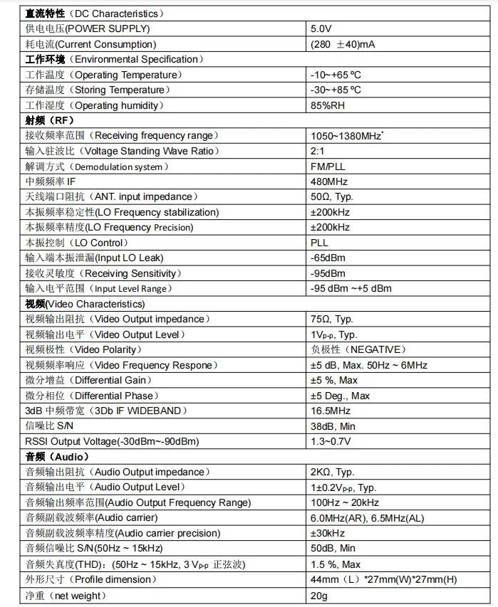
Operating specifications: the current consumption is 5V, with a temperature range of -65°C to +85°C for storing. Operating humidity is within 30-80% RH. The receiving frequency range is from 1050 MHz to 1380 MHz. Voltage Standing Wave Ratio (VSWR) is 2.1:1. The demodulation system uses FMPLL with an IF frequency of 48 MHz, and the modulation method is FM.
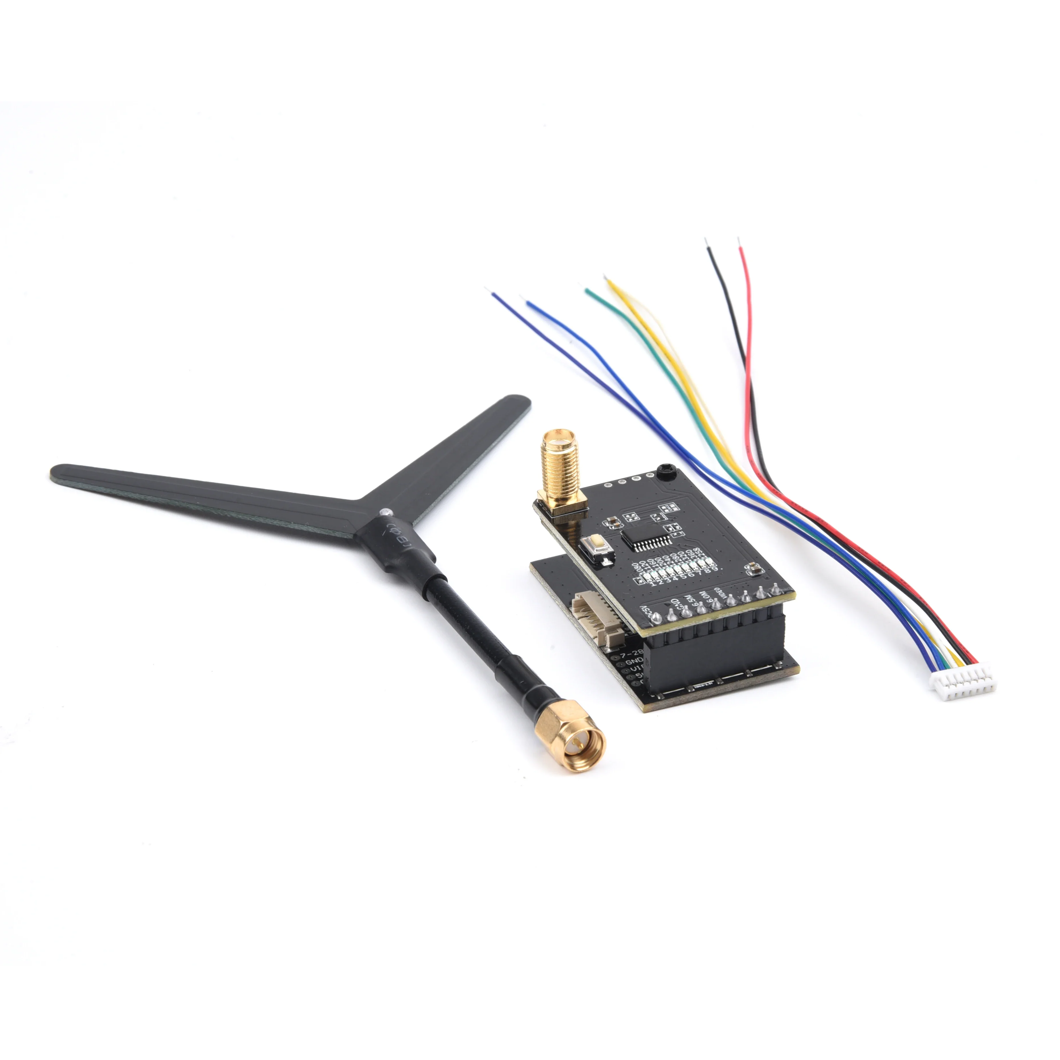
Package included:( send it as your choice)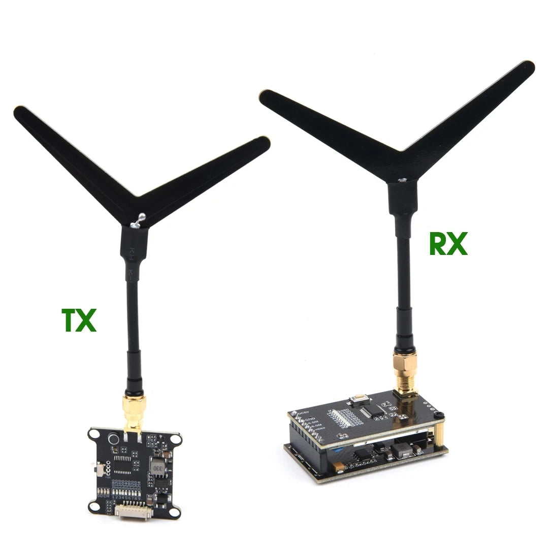


-
Customer ReviewsNo comments